真空管式ポータブルFMラジオ
2004年12月完成
Tube Portable FM radio
Completed Dec.
'04
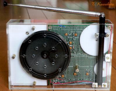
大きさ :184mmx122mmx45mm(つまみ部除く)
size : 7.2"x4.8"x1.8"(except protrusion of
knob)
特徴
:
・(多分あまり例の無い)真空管式ポータブルFMラジオ。もちろんAMも受信できます。
・FCZ研コイル等、入手容易な部品だけで構成。
・一般的な真空管式AMポータブルラジオと同程度の大きさ
Features
:
*This is TUBE PORTABLE FM
RADIO.
Of course this radio can also receive AM broad cast.
*This radio is
cosists of parts that can be easily
obtained
*About the same size with ordinary Tube AM portable
radio.
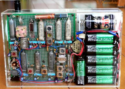
裏側
Back
使用球 :
5678
x 7 5676 5672 合計9球
Tube
line up : 5678x7 5676
5672 total
9tubes
回路構成 Block diagram
:
・
FMチューナ部:
局部発振 混合 中間周波増幅(3段)
検波(レシオ検波)
5676
5678 5678x3 ゲルマニウムダイオードx2
・AMチューナ部
周波数変換
中間周波増幅
検波
5678
5678
ゲルマニウムダイオード
・オーディオアンプ部:
電圧増幅
電力増幅
5678
5672
Block diagram
:
*FM tuner
part:
Local oscillator Mixer IF-AMP (3-stages)
Detector(Ratio detector)
5676
5678 5678x3
Germanium diodex2
*AM tuner
part:
converter IF-AMP. Detectot
5678
5678 Germanium
diode
*Audio-AMP
part:
AF-AMP. Power
AMP.
5678
5672
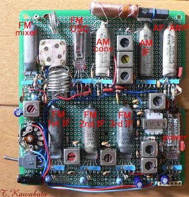
基板 部品面側
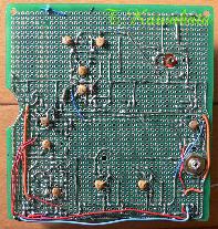
基板 パタン面側
PWB Parts
side
PWB Pattern side
回路図
※回路図はあくまで参考です。利用は自由としますが利用により生じるいかなる結果にも責任を負いません。
schematic
Schematic can be used freely.
But it is only a reference, and I can't be responsible for any
results.
回路について
FMチューナ部:
真空管式のポータブルFMラジオというものについては技術資料がほとんどなく、また、私自身も専用ICを使用したもの以外、FMラジオを作った経験がないので、回路はほとんどカットアンドトライで決めており、理屈の上からは変なところもあるかもしれません。
フロントエンド部は独立した局発の出力を混合管のG1で混合する形式になっており、高周波増幅はありません。普通の真空管式FMラジオでは双3極管を使い、片方でグリッド接地型の高周波増幅(バッファー?)、片方で発振と混合という形式が多いのですが、電池管ではグリッド接地型の回路は難しいし、1本で発振と混合を行う回路も難しそうなので、グリッド接地型の回路も不用で発振さえすればそこそこ動作する、このような回路にしました。
中間周波増幅回路は3段で、リミッタ、AGCはありません。3段目以外、回路図のように単同調で次段とC結合されています。これは部品点数を減らすためで、大きな意味はありません。プレート負荷の同調コイルはトランジスタAMラジオ用のものの改造品ですが、10.7MHzのFCZ研コイルでも大差ありません。フィラメントの回路には全てLCフィルタを入れています。
検波(ディスクリミネータ)はレシオ検波で、検波用のコイルは10.7MHzのFCZ研コイルをそのまま使っています。(球の負荷側のコイルは同調Cの値を変えています。)FCZ研コイルをそのまま使う関係で、ちょっと変わった回路になっています。検波回路はいくつか試したのですが、試した中ではこの回路が最良でした。
AMチューナ部:
普通、AMのIF増幅はFMのIF増幅と、球が共用になっているものですが、このラジオは私にとって事実上初めてのFMラジオだったので、トラブルを避けるため、AMチューナはFMチューナとは完全に独立になっています。回路は当ホームページの、他のラジオでよく使っている回路そのままで、5678による5極管コンバータによる周波数変換の後、5678による中間周波増幅、ダイオード検波となっています。中間周波増幅回路にはAGCを掛けています。
オーディオアンプ部、他:
特に変わったところはなく、5678による電圧増幅の後、5672による電力増幅を行っています。
AMとFMの切り替えは、各チューナの出力をこのオーディオアンプの入力のところで切り替えることにより行っています。また、使用していない側のチューナの球はフィラメントを消灯して、消費電力を減らしています。
出力管のバイアスは普通のポータブルラジオのように全B電流から取っているので、実はFMとAMではバイアスが変化してしまいます。適正バイアスは−3.8Vなのですが、FMのときは−4.5V、AMでは−3.1V位になっています。途中でこれに気がついて、補正する回路を設けようとも考えたのですが、聴感上違和感がなかったのでそのままにしています。
About schematic:
*FM tuner part:
The circuit
was determined by cut and try. Because I had no experience of making FM radio
except using exclusive use IC. And more I had almost no technical
informations about tube portable FM radio. So, the circuit may have odd
part.
Front end part is the type where output of independent local oscillator
is mixed at G1 of mixer tube, have no RF-AMP. Many of front end of ordinary
(AC-powered) tube FM radio are the type where twin triode is used and its one
part works as grid grounding RF-AMP and the other form a oscillator-mixer. But
in case of Battery tubes, grid grounding type RF AMP and oscillator-mixer seem
to be difficult to realize. On the other hand, I thought this type of front
end circuit will work surely. Its only difficulty is local oscillator oscillates
or not.
IF AMP has 3 stages, has no limiter and AGC. Except for last stage, a
stage is coupled to following stage with capacitor, as shown in schematics. But
it has no particular meaning, only to reduce parts used. Tuning coils of plates
load are reconstructed from IFT for transistor AM radio, and so called "FCZ lab
coil"(10.7MHz) are also suitable.( "FCZ lab coil" are coils for transistor IF
and RF AMP circuits, common in Japan and have various types.) LC filter is
altogether put into the circuit of a
ilament.
Detector (discriminater) is ratio detector. Coils for discriminater are
10.7MHz "FCZ lab coil". Capacitance of tuning capacitor of discriminater coil of
plate load of last IF AMP stage is changed. To make up ratio detector using FCZ
lab coils almost as it is, it is rather unusual circuit. Although some detection
circuits were tried, this circuit was best in having
tried.
*AM tuner part:
Usually tube for AM IF AMP of
FM/AM radio is shared with tube for FM IF AMP. But this radio is first FM radio
as a matter of fact for me. So, in order to avoid trouble, AM tuner is
completely independent from FM tuner. Its circuit diagram is almost the same
with other radios posted on this web site. It consists of pentode converter
using 5678 and IF AMP using 5678 and detector with germanium diode. AGC is
applied on IF AMP.
*Audio amplifier part, others:
Audio AMP circuit have
no unusual part, and consists of voltage AMP with 5678 and power AMP with 5672.
Band select (AM or FM)is done by switching output of each tuners at volume
control of this audio AMP. And tubes of one tuner not using are turn off their
filaments to reduce power consumption. Since the bias of an output
tube is taken from all B current like ordinary portable radio. So, voltage of
bias will change by FM or AM. Although proper bias is -3.8V, by -4.5V at
AM, it is -3.1 V at the time of FM.
I noticed and planned
to add some circuit to correct this. But I did not have incongruity of sound,
and so, I leaves it as it is.
電池 :
・A電池:単2 1個 1.5V
・B電池:006P x
6個 54V
Batteries requirement:
*A-Battery : C-cell x 1
1.5V
*B-Battery : 6F22(9V) x 6
54V
使用部品 :
・主要部品はトランジスタ用(FCZ研コイル他)を使用。コイル類の巻線は変更。
・出力トランス−−ST30(相当品)の改造(巻線の変更)
−−もともとのコイルをDC抵抗がもとの70%程度になるまでほとき、
生じたスペースにφ0.2線を75T位巻きSP用の2次コイルとする。
・S付VR 1MΩ スイッチ1回路1接点を2回路1接点に改造
Parts:
*Main parts are parts for transistor radio. All coils are
altered.
*Output transformer is remake of ST-30 (its equivalent
type).
--Remove original part of coil so that its DC
resistance
become 70% of original winding. And wind 0.2mm wire 75T on it,
to be secondary
winding.
*Volume control 1Mohms with
SW
--originally
have 1 pole 1throw switch, convert into 1 pole
2throw.
外装 :
フロント3mm、他2mm厚の透明アクリル板で自作
Casing : Hand made, made of
clear acryl plate. Thickness; front 3mm, others
2mm.
シャーシ :
金属製のシャーシはなし。ユニバーサルプリント基板を使用
Chassis : Using PWB, has no metal chassis
つまみ類 :2mm厚のABS板より削り出し
Knobs : Turnings, made of acryl
plate thickness of 2mm.
外装、構造 :
1枚板の前面板に全ての部品が取り付けられ、後方から箱型をしたカバーをかぶせるような構造になっています。このためカバーを外し、電池を取り出すと大半の部品が剥き出しになりこの状態メンテナンスすることができます。このカバーは嵌め込みで固定されています。回路基板もこの前面板に取り付けられています。回路基板には球(のソケット)、IFT、出力トランス等が取り付けられています。
Casing and construction :
All parts including loud
speaker are fixed on to Front plate. And cover this body with box shape back
cover. So, all parts can be maintained, by removing this back
cover. This cover is snap fitted to front plate. PWB are also
fixed to this front plate. Sockets of tubes and IFT etc. are fixed to
this PWB.
性能、他
:
真空管式ポータブルFMラジオを作ろうと思い立ったのは実は2001年春のことなのですが、真空管式ポータブルFMラジオなどというものに関する技術資料は当然ながらほとんどなく、ただ時間だけが過ぎ、ようやく試作に漕ぎ着けたのが2003年の暮れで、試作の結果何とかやれそうな目処が立ったのが2004年の9月に入ってからでした。
10月から実際の製作に入り、部品の準備(コイルの巻きなおし等)、回路部分の組み立て配線、外装の製作、にそれぞれ1ヶ月、実際の製作開始から計3ヶ月で完成しました。
感度、音質はそこそこで、当地では鉄筋の室内で、ロッドアンテナ(全長70cm位)をフルに伸ばさなくても、NHK−FM(88.1MHz)、fm osaka(85.1MHz)、FM 802(80.2MHz)が良好な音質で受信できます。FM CO・CO・LO(76.5MHz)、α−Station(89.4MHz)とNHK総合(TV 2ch)の音声はアンテナをフルに伸ばして、状態のよい位置を探せばそこそこの音質で受信できます。
AFCがないせいもありますが良好な音質で受信するには正確にチューニングする必要があります。また、電池の電圧変動で、局発の周波数が若干変動するようです。また、高周波増幅が無いので、アンテナに対するボディエフェクトが心配されたのですが、実用的には問題の無いレベルでした。
AM部分の性能はほぼ標準的なもので、内蔵のバーアンテナのみで鉄筋の室内で当地(大阪府寝屋川市)の地元局は全て受信でき、同条件で夜間は遠距離局も受信できます。
消費電流はFM時、A電流が420mA、B電流が7mA位、AM時、A電流が200mA、B電流が5mA位で、特にFM時のA電流はかなり多いですが、アルカリ電池を使用すれば10時間程度の寿命が期待され、何とか実用になります。
Performance and
others :
Actually, when I planned to make tube portable FM
radio was spring of 2001. But then I had almost no technical informations about
such a kind of radio. And only time has merely passed. The end of 2003, I
managed to made a trial production. And based on the results of this trial
production, I had the prospect to make this radio in September, 2004. Actual
manufacture was started from October 2004. I took 1 month respectively to
prepare (rewound coils etc.) parts, assemble and wire of a circuit board, and
manufacture the exterior. And all were completed in 3 month.
Sensitivity and
sound quality is not so bad. In the interior of a room of a ferroconcrete
structure NHK-FM (88.1MHz), fm osaka (85.1MHz), and FM 802 (80.2MHz) be received
by good sound quality here (Neyagawa city Osaka Japan) even if its telescopic
antenna (about 70cm in full length)is not fully extended. If the antenna
extended fully, and the good position is looked for, FM CO-CO-LO (76.5MHz),
alpha-Station (89.4MHz), and the sound part of NHK-TV (TV 2ch, 102MHz) can be
received, but sound quality is not so good.
Because of having no AFC,
it is necessary to tune up correctly for receiving by good sound quality. And
frequency of local oscillator fluctuate according to fluctuation of voltage of
batteries. And because of having no RF-AMP, so called "body effect" to the
antenna was worried about, but it was the level of satisfactory
practical.
The performance of AM portion is almost standard, All
stations within about 30 miles can be received with built-in stick antenna in my
home (ferroconcrete structure). And at night some distant station can be
received.
Concern with power consumption, when receiving FM, A current is
420mA and B current is about 7mA, and when receiving AM, A current is 200mA and
B current is about 5mA respectively. Especially, A current for receiving FM is
quite much. But if an alkaline type battery is used, the A battery life of about
10 hours will be expected and it will be used somehow
practical.
戻る
Back