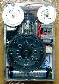
正面 裏側
*電池の上の白い物はDC-DCコンバータ
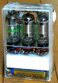
Front Back
*White block over batteries is
DC-DC converter unit for B-voltage supply

大きさ:100mmx65mmx34mm(つまみ部除く)
Size : 3.9"x2.6"x1.3"(except protrusion of
knob)
特徴:
正面
裏側
*電池の上の白い物はDC-DCコンバータ
Front
Back
*White block over batteries
is
DC-DC converter unit for B-voltage supply
使用球
: 1T4 x2 1DN5
Tube line up : 1T4 x 2
1DN5
回路構成:周波数変換 中間周波増幅 検波 電圧増幅 電力増幅
1T4 1T4 1DN5(D) 1T4
1DN5(P)
※電圧増幅はレフレックスでIFと共用
Block diagram:
Converter IF-AMP
2nd-Detector AF-AMP Power
AMP
1T4
1T4
1DN5(D)
1T4
1DN5(P)
*AF and IF are amplified in 1 tube using reflex circuit
回路図
※回路図はあくまで参考です。利用は自由としますが利用により生じるいかなる結果にも責任を負いません。
Schematic
*Schematic is only a reference and can be use
freely But I can't be responsible for any result.
使用部品:・主要部品はトランジスタ用を使用。コイル類の巻線は変更。
・出力トランス−−ST30(相当品)の改造(巻線の変更)。
・S付VR 50KΩ スイッチ1回路1接点を2回路1接点に改造
Parts: *Main parts are parts
are parts for transistor radio. All coils are
altered
*Output transformer--Remake of ST-30 (equivalent
type)
*Volume control 50kohms with
SW
--originally have 1 pole 1throw switch, convert
into 1 pole 2throw
外装 :
シャーシ :
1mm厚のアルミ板で自作つまみ類 :
1mm厚のABS板より削り出し外装、構造 :
スピーカと電池ボックス以外 の部品はアルミシャーシに取付けられています。アルミシャーシは上が開いたコの字の形をしています。球(のソケット)とIFTは水平な部分に取り付けられ、その他の部品は左右の垂直に立った部分に取り付けられています。
IFTは7mm角のトランジスタラジオ用の巻線変更品ですがこれを金属製の円筒に入れて、真空管用のIFTのような感じの外観にしています。この金属製の円筒は単4電池の金属外装を改造して作っていますが、最近金属外装の単4電池がほとんどなくなってしまったので入手にちょっと苦労しました。
バリコンと球はどうしても重なる部品配置とならざるを得ず、ラジオ全体の厚さは球の直径とつまみを含むバリコンの全高で決まってしまいます。このため少しでも薄くするためバリコンのシャフトは限界まで短く切り詰めています。ラジオの幅65mmは使用したケースの寸法から変更のしようがないのですが厚さはある程度調整が利くのでこれが納まるぎりぎりの寸法として厚さ34mmとしています。幅65mmで厚さ34mmというのは通常のワイシャツの胸ポケットに入るほとんどぎりぎりの寸法です。「ポケットラジオ」にとってワイシャツの胸ポケットに入るかどうかはかなり重要な要素なのでちょっとこだわってみました。
Casing and structure
:
All parts except loud speaker and batteries are fixed to chassis
made of aluminum plate. This chassi has shape like letter "U". Sockets of tubes
and IFT's are fixed to bottom (horizontal) part of this chassis, and the
other parts are fixed to two vertical parts of this chassis.
IFT's are made
by converting IFT's for transistor. And I made case using metal shell of
worn out AAA-cells and let the body of IFT into the case. Thus appearance of the
IFT's become suitable for tubes. But to my regret, recently, AAA-cells with
metal shell are rather difficult to obtain.
Converter tube must overlap
with variable capacitor. So, total thickness of this radio will be
determined by diameter of tubes and total height of variable
capacitor. To make this radio as thin as possible, I cut down the shaft of
variable capacitor as short as possible. Width of this radio 2.6" is determined
by the size of existing case that I use for case of this radio, and this can not
be changed. But thickness will be changeable to some extent. And I determined
the thickness to be 34mm (1.3"). This thickness of 34mm is minimum size that can
contain overlapped tube and variable capacitor. And in case of width of this
radio is 65mm(2.6"), this thickness of 34mm is almost maximum size that can go
into shirt pocket. Thus, I realized "shirt pocket portable" using
mT-tubes.
性能、他 :
SMT管を使用すると小型に作ることができるのはよいのですがSMT管は真空管としてはあまり一般的でなかったので「真空管式」という雰囲気にやや乏しいのが難点です。このため真空管の形状として最も一般的だったMT管を使用してポケットサイズのラジオを作りたいと考えるようになり、このラジオを製作しました。
実はこのラジオは2代目で、これとほとんど同じものを2001年8月にも完成させています。しかし一代目の方は感度が今一つな割に電波が強いときに音がひずみやすいという問題点があったのでその点を解決すべく今回のものを製作しました。前回のものはVRがAF増幅の後に入っていたので強電界では飽和しやすかったのですが今回のものは前述のようにIFT-A1とIFT-A2の間に入れたので強電界でもほとんど問題なくなりました。
感度もそこそこよく、内蔵のバーアンテナのみで鉄筋の室内で当地(大阪府寝屋川市)の地元局は全て実用的に受信できます。同条件で夜間は遠距離局も受信できます。電圧増幅管を出力管として使用しているので大音量は出ませんが6畳くらいの室内で数人で聞くというような感じの使い方には十分な音量です。
Performance and others:
sing subminiature tubes, We can make very small radio. But most
Japanese have never seen subminiature tubes.
Because before subminiature
tubes, transistor era had come. So, Most Japanese will not recognize radios
using subminiture tubes as "Tube radio" at first glance. On the other hand,
mT-tubes are so common that many of Japanese know the shape. So, I planned to
make "shirt pocket portable" using this mT-tubes.
To tell the truth, this
radio is second one. I've made almost same radio before. But it had insufficient
sensitivity and Its sound tend to distort when input signal is large. I wanted
to correct this weak point and planned to make this radio. Volume control
of the previous radio was put between AF-AMP and power AMP. And so, output
of AF-AMP saturate when input signal is large. But this time, volume
control is put between IFT-A1 and IFT-A2 and corrected the weak
point
All stations within about 30 miles
can be received with built-in bar antenna in my home (ferroconcrete
structure). And at night some distant station can be received.
Because
AF-AMP tube 1DN5 is used as audio output tube, audio output is small. But it has
enough volume for listening by few person in small room.