SMT管式レフレックス3球スーパー
2001年6月完成
3-SmT
tubes reflex super het
Completed Jun. '01
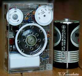
・右は比較用の単一電池
Right:
D-cell for size comparison
大きさ :80mmx55mmx23mm(つまみ部除く)
size : 3.3"x2.2"x0.9"(except protrusion of
knob)
特徴
:
・スピーカ内蔵で4球スーパ相当の性能でありながら名刺サイズよりも
小さい(厚みは名刺より厚いですが)超小型
・ほぼ実用レベルの性能
Features
:
*Although almost business card size (sorry but much
thicker),
contains loud
speaker
*Practically usable--About the same
performance
with standard 4-tubes portable super
het.
正面
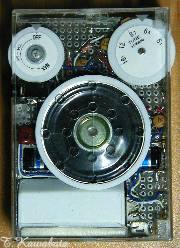
裏側
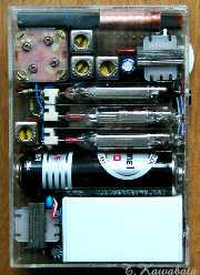
*右下の白い物はDC-DCコンバータ
Front
Back
White block right-under is
DC-DC
converter unit for B voltage supply.
使用球 :
5678 1AJ5 1AG4
Tube line
up : 5678 1AJ5
1AG4
回路構成 Block diagram
:
周波数変換 中間周波増幅
検波 電圧増幅
電力増幅
5678 1AJ5(P) 1AJ5(D)
1AJ5(P)
1AG4
※電圧増幅はレフレックスで中間周波増幅と共用
Block diagram
:
converter
IF-AMP. 2nd detectot
AF-AMP. Power
AMP.
5678
1AJ5(P)
1AJ5(D)
1AJ5(P)
1AG4
AF and IF are amplified in 1 tube (1AJ5-P) using reflex
circuit
回路図
※回路図はあくまで参考です。利用は自由としますが利用により生じるいかなる結果にも責任を負いません。
schematic
Schematic can be used freely.
But it is only a reference, and I can't be responsible for any
results.
回路について
周波数変換は5極管コンバータを使用していますが、これは私がこの種のラジオを作りはじめたとき、SMT管のコンバータ球が入手できなくて5極管コンバータを使用したなごりみたいなもので大きな意味はありません。5678のG1に接続されている4pFのCは発振周波数がANT側の同調周波数に引き込まれるのを防止するための中和コンデンサで、このコンデンサの容量は球により調整する必要があるのですが、この種のSMT管の場合は4pFでうまく動作する場合が多いようです。
1AJ5は2極部のPと5極部のG1の引き出し線が接近しているのでそのままだとこの影響により発振します。この対策のため、IFT−Bは5極部のPと2極部のPで位相が逆になるように巻き線し、1AJ5の5極部のPとG1の間に入ってるCで中和しています。このCは現実には平行する2本のリード線です。
VRは小型のものは100kΩのものしか入手できなかったので入れる場所に悩み、図のようにAF増幅の後に入れています。このため、強電界で音が歪みやすい傾向があります。
検波とAFの間にDCカット用のCがありませんがこれは1AJ5(P)で一緒に増幅されるAFによりIFが変調されることにより起きる発振を防止するためです。
イヤホンはセラミックタイプのものを使用し、イヤホンジャックにイヤホンを挿入すると出力管を消灯し、消費電力を減らすようにしています。
About schematic:
I used pentode converter for frequency
changer. Subminiature converter tube (like 2G21 or 1V6) is rather difficult
to procure in Japan. And so, I often use pentode converter. Except this, I
have no special reason why I use pentode converter.
Capacitor of 4pF
connected to G1 of 5678 is neutralizing capacitor. It avoid oscillating
frequency being pulled into frequency of antenna tuning circuit. Capacitance of
this capacitance of this capacitor needs to be adjusted by tube. But
In case of subminiature tubes like 5678, usually it works well at
4pF.
Plate of diode and lead out wire of pentode section of
1AJ5 are close to each other. So, IF-AMP will oscillate harmfully. To avoid
this oscillation, I wind IFT-B so that phase at plate of pentode and at
plate of diode become inverted each other, and neutralize by capacitor
between plate and G1 of pentode of 1AJ5. Actually, this capacitor is two
parallel wire.
I could obtain small volume control of only 100kohms. So,
I put volume control after AF-AMP. But in this arrangement, audio output tend to
distort when input signal is large.
In reflex circuit, IF signal is tend
to be modulated by AF signal which is amplified in same
tube. When input signal is large, this modulation may cause harmful audio
oscillation. To avoid this harmful audio oscillation, there is no
coupling capacitor between detector and AF-AMP.
This radio uses ceramic type
earphone. And when earphone plug is inserted, turn off output tube(1AG4),
and decrease power consumption.
電池 :
・A電池:単3 1個 1.5V
・B電池:コインリチウム電池CR2025x15個 45V
※B電池は通常はDC−DCコンバータユニットを使用
Batteries requirement:
*A-Battery : AA cell x 1
1.5V
*B-Battery : Coin lithium cell CR2025 x 15
45V
I've made DC-DC converter unit for B-voltage
supply
and use it for daily use.
使用部品 :
・主要部品はトランジスタ用を使用。コイル類の巻線は変更。
・出力トランス−−ST30(相当品)の改造(巻線の変更)
−−もともとのコイルをDC抵抗がもとの70%程度になるまでほとき、
生じたスペースにφ0.2線を50T位巻きSP用の2次コイルとする。
・S付VR 100KΩ スイッチ1回路1接点を2回路1接点に改造
Parts:
*Main parts are parts for transistor radio. All coils are
altered.
*Output transformer is remake of ST-30 (its equivalent
type).
--Remove original part of coil so that its DC
resistance
become 70% of original winding. And wind 0.2mm wire 50T on it,
to be secondary
winding.
*Volume control 100kohms with
SW
--originally
have 1 pole 1throw switch, convert into 1 pole
2throw.
外装 :
フロント2mm、他1mm厚の透明アクリル板で自作
Casing : Hand made, made of
clear acryl plate. Thickness; front 2mm, others
1mm.
シャーシ :
金属製のシャーシはなし。ユニバーサルプリント基板を使用
Chassis : Using PWB, has no metal chassis
つまみ類 :1mm厚のABS板より削り出し
Knobs : Turnings, made of
ABS plate thickness of 1mm.
外装、構造 :
「超小型SMT管式4球スーパ」と同様スピーカを含む回路部品全てが1.6mm厚のガラエポユニバーサル基板に取り付けられて、これがケースにねじ止めされた構造になっています。このため、このねじを外すと回路基板をそっくり取り出してメンテナンスすることができます。球はICソケット改造のソケットに挿入されており、各球の間にシールド板があります。
ケースは1mm厚アクリル板で作られていますが前面のみ2mm厚になっています。全体を1mm厚のアクリル板で作るとちょっと頼りない感じなのですが、このように前面のみ2mm厚とすることにより比較的しっかりした感じの外装に仕上がっています。
Casing and construction
:
All parts including loud speaker are fixed on to PWB thickness of
1.6mm. And this PWB is fixed to Casing with screws. So, PWB and all parts on it
can be took out and maintained, by removing these screws.
All tubes are
inserted in to sockets. This sockets are remake of IC sockets. There are shield
plates between each tubes.
Casing is made of acryl plate thickness of mainly
1mm. Only front plate has is thickness of 2mm. If all are made of
acryl plate thickness of 1mm, it will be weak and easy to break. But by this
way, casing become solid and reliable.
性能、他 :
「超小型SMT管式4球スーパ」は非常に小型にできたのはよかったのですが電池寿命等、やや実用的とは言い難かったので、大きさはこれより多少大きくても良いから実用的な性能のものを目標に製作しました。
内蔵のバーアンテナのみで鉄筋の室内で当地(大阪府寝屋川市)の地元局は全て受信でき、同条件で夜間は遠距離局も受信できます。感度、音量共、この大きさのラジオとしてはほぼ実用レベルです。ただし前述のよに強電界で音が歪みやすいのが難点です。
DC−DCコンバータ使用時のA電池(アルカリ単3 1個)の電池寿命は4時間程度で、十分とはいえないのですがデジカメの普及のおかげでアルカリ単3の実売価格が非常に安いので日常、常用しても電池代はほとんど気になりません。
Performance and others
:
" Mini size 4-SmT tubes super het " is very small but it have only insufficient performance for practical use. So, I
wanted to make radio that have sufficient performance for practical use,
permitting rather larger size.
All stations within about 30 miles can
be received with built-in bar antenna in my home (ferroconcrete
structure). And at night some distant station can be received. Sensitivity
and volume are sufficient for practical use as radio of this small
size. But audio output tend to distort when input signal is strong.
Life
of A-battery is about 4 hours with alkaline type battery in case of
using DC-DC converter for B voltage supply (power for DC-DC
converter is supplied from A-battery). This battery life is rather short,
but recently alkaline type AA-cell can be bought at very low price. So
cost of daily use is not expensive.
戻る
Back