超小型SMT管式4球スーパー
2001年4月完成
Mini size 4-SmT tubes super het
Completed April.
'01
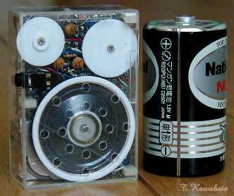
・右は比較用の単一電池
Right: D-cell for size comparison
大きさ:65mmx45mmx23mm(つまみ部除く)
Size : 2.6"x1.8"x1.3"(except protrusion of
knob)
特徴:
・スピーカ内臓の4球スーパでありながら100円ラジオと比較しても
かなり小さい超小型。私が作ったスピーカ付のスーパーとしては 現
時点では最も小型。
・補聴器用の超小型SMT管を使用。
・B電池はコインリチウム電池7個21Vの低電圧で動作
Features
:
*Although much smaller than business card size (sorry but
much
thicker), contains loud speaker. And the smallest radio I made.
*Using
hearing aid
tubes.
*Low B-voltage 21V, using coin-lithium cell
x 7
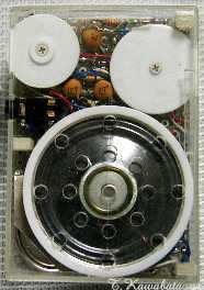
正面
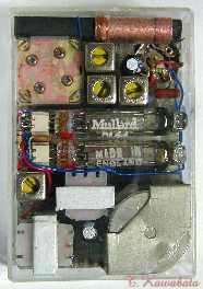
裏側
*2本見える球はDL64。 CK6418はこの下
Front
Back
2 tubes in photograph are
DL64
2-CK6416s are below these tubes
使用球
: CK6418 x2 DL64 x2
Tube line up : CK6416 x 2 DL64 x
2
回路構成:
周波数変換 中間周波増幅 グリッド検波 電力増幅
CK6418 CK6418 DL64
DL64
Block
diagram: Converter IF-AMP
Grid-Detector Power
AMP
CK6418
CK6418
DL64
DL64
回路図
※回路図はあくまで参考です。利用は自由としますが利用により生じるいかなる結果にも責任を負いません。
Schematic
*Schematic is only a reference and can be
use freely But I can't be responsible for any
result
回路について:
この種の球の変周管や検波、電圧増幅用の2極5極管は存在しないので周波数変換は5極管コンバータとし、また、第2検波はグリッド検波としています。
検波管の負荷はトランジスタラジオ用のチョークトランスST-30(の相当品)を使用しチョーク負荷としています。
また、検波管のグリッドリークからAGC電圧を取り出し、中間周波増幅管にAGCをかけています。
コンバータ回路のL5と4pFのCは局部発振の周波数がアンテナ側の同調周波数に引き込まれるのを防止するための中和回路を構成しています。このコンデンサの容量は球により調整する必要があるのですが、この種のSMT管の場合は4pFでうまく動作する場合が多いようです。
使用球は手持ちの球の関係でCK6418とDL64を2本づつ使用していますがCK6418またはDL64を4本使用してもよいです。どちらの球も低いB電圧での動作に適しています。
About schematic :
Because both converter tube and
diode-pentode tube for 2nd detector and AF-AMP are not exist in this type of
tubes, I use pentode converter for frequency changer and grid detector for
2nd detector.
I used choke coil for plate load of 2nd-dertector. For
this plate load choke, I use ST-30 (its equivalent type) transformer.
Originally ST-30 is a transformer for transistor radio.
AVC signal
is obtained from grid leak resistor of detector tube and I applied AVC to
IF-AMP.
Capacitor of 4pF connected to G1 of converter tube
and L5 forming neutralizing circuit. It avoid oscillating frequency being
pulled into frequency of antenna tuning circuit. Capacitance of this capacitance
of this capacitor needs to be adjusted by tube. But In case of subminiature
tubes, usually it works well at 4pF.
I used two CK6418s and two DL64s
because of my stock. But It will work well using CK6418 x 4 or DL64 x
4.
Both CK6418 and DL64 are suitable for low B-voltage
operation.
電池: ・A電池:コインリチウム電池CR3032 x1個 3V
・B電池:コインリチウム電池CR2016
x7個 21V
Batteries
requirement:
*A-batteries : CR-2032 coin lithium cell x 1
3V
*B-batteries : CR-2016 coin lithium cell x 7
21V
使用部品:・主要部品はトランジスタ用を使用。コイル類の巻線は変更。
・出力トランス−−ST30(相当品)の改造。−−本来の巻線の上にφ0.2
線を40T巻きSP用の2次巻線とする。
・S付VR 100KΩ スイッチ1回路1接点を2回路1接点に改造
Parts:
*Main parts are parts for transistor radio. All coils are
altered.
*Output transformer is remake of ST-30 (its equivalent
type).
--wind 0.2mm wire 40T on original winding, to be secondary
winding.
*Volume control 100kohms with
SW
--originally
have 1 pole 1throw switch, convert into 1 pole
2throw .
外装 :1mm厚の透明アクリル板で自作
Casing : Hand made,
made of clear acryl plate thickness of 1mm.
シャーシ :金属製のシャーシはなし。ユニバーサルプリント基板を使用
Chassis :
Using PWB, has no metal chassis
つまみ類 :1mm厚のABS板より削り出し
Knobs : Turnings made of
ABS plate thickness of 1mm.
外装、構造 :
スピーカを含む回路部品全てが1.6mm厚のガラエポユニバーサル基板に取り付けられて、これがケースにねじ止めされた構造になっています。このため、このねじを外すと回路基板をそっくり取り出してメンテナンスすることができます。
球はICソケット改造のソケットに挿入されており、検波管と出力管の間以外は各球の間にシールド板があります。
B電池は基板の部品面側に設けられた電池ホルダに7個重ねて斜め下方からスライドさせて入れるようになっています。A電池は同様の構造の電池ホルダでB電池の真下にこれとほとんど重なって入るようになっています。
Casing and construction :
All parts including loud speaker
are fixed on to PWB thickness of 1.6mm. And this PWB is fixed to Casing with
screws. So, PWB and all parts on it can be took out and maintained, by removing
these screws.
All tubes are inserted in to sockets. This sockets are remake
of IC sockets. There are shield plates between each tubes.
Battery holders
are formed on part of PWB. B-battery holder are parts slide of PWB
and A-battery holder are just under it. And 7-B-cells are stacked and
slid into this holder. A-cell are also slid
in.
性能、他
:
CK6418やDL64は通販で入手したのですが入手して初めて通常のSMT管より小型であることを知り、また低電圧での動作に適しているのでこれを使用して、それまで私の作ったもののなかで最小だった「 SMT管式レフレックス2球スーパ」よりも更に小さな真空管式ラジオを作りたいと思いこのラジオを製作しました。
内蔵のバーアンテナのみで鉄筋の室内で当地(大阪府寝屋川市)の地元局は一応全て受信でき、同条件で夜間は遠距離局も若干受信できますが、感度、音量共、それ程用よくはなく、同条件で実用的に聞けるのは地元局の内、3局位です。
コインリチウム電池CR−3032は公称の容量が200mAh位あり、A電流は計20mAなので十分な寿命があると考えていたのですが公称容量は負荷が0.1mA位の場合での値で、20mAという値はこの電池にとってかなりの重負荷のようで実際のA電池の寿命は1時間程度しかありませんでした。
CR−2016をB電池に使用するのは特に問題なく、完成後A電池は何度も交換していますがB電池は完成から2年近く経ってもまだ1度も交換したことがなく20V位の電圧があります。
Performance and others :
I bought DL64 and CK618 from
mail-order firm. But I've never know that these tubes are smaller than ordinary
subminiature tubes like 5678 until they arrive. And I know
that they both are suitable for low B-voltage operation. And
I planned to make very small radio using these tubes.
All stations within about 30 miles can be received with
built-in bar antenna in my home (ferroconcrete structure). And at
night some distant station can be received. But performance is not so
good.
Nominal capacity of CR-2032 is about 200mA/h. And total A-current
is 20mA. And before I make this radio I thought it will
have sufficient A-battery life. But really, A-cell runs only 1
hour. Nominal capacity of CR-2032 is defined at current of about 0.1mA. And
20mA is too heavy load for this cell. On the other hand, B-batteries
have enough life.
戻る
Back