2002年8月完成
2-ST tubes super het
Completed Aug. 2002
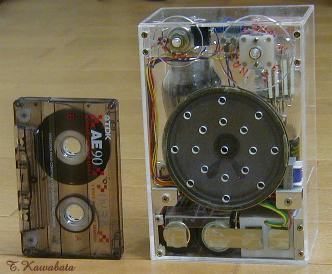
・左は比較用のオーディオ用カセット
Left: Audio cassette for size comparison
大きさ :146mmx96mmx61mm(つまみ部除く)
Size : 5.8"x3.8"x2.4"(except protrusion of knob)
ST管式2球スーパー
2002年8月完成
2-ST tubes super
het
Completed Aug. 2002
・左は比較用のオーディオ用カセット
Left: Audio cassette for
size comparison
大きさ :146mmx96mmx61mm(つまみ部除く)
Size :
5.8"x3.8"x2.4"(except protrusion of
knob)
特徴:
・たった2球でほぼ4球スーパ相当の性能。
使用球
: 1E7G 1F6
Tube line up :
回路構成:
周波数変換 中間周波増幅 検波 電圧増幅 電力増幅回路図
回路について:
1E7Gの片方で周波数変換を行うため周波数変換回路は5極管コンバータとなっています。この回路はフィラメントを直接接地できるので、このように複合管の片方で周波数変換を行う場合に便利です。電力増幅管である1E7Gによる周波数変換は変則的ですが結構安定かつ高感度に動作しています。
電力増幅回路は、B電圧が低いのでグリッドリークによるバイアスのみで使用しています。
このラジオはAFがレフレックスでIFと共用なのでAF出力にIFの成分が含まれ、これが出力管に入ると出力管のPにこの成分が出てくることになります。出力管は変周管と同じ球で双方のPが非常に近接しているので、出力管のPにIFの成分がでてくると近接している双方のPの静電容量でIFの出力が入力側に戻ることになり発振を起こします。AFと電力増幅の間に入っているフィルタはこの対策で、AFからIFの成分を十分取り除くようにしています。
検波とAFの間にDCカット用のコンデンサが入っていませんがこれはレフレックス特有の発振を防止するためです。
球のフィラメンと電圧は2Vなので電圧をあわせるためフィラメント回路に電圧ドロップ用の抵抗が入っています。この抵抗値ではA電池が新品の場合フィラメント電圧は定格より20%位高くなります。1E7Gはフィラメント電流が大きいのは難点です。
About schematic:
Frequency changer is pentode converter,
in order to use 1E7G as a converter tube. In this pentode converter circuit,
filament of tube can be connected GND and F+ directly, and advantageous to use
one part of multiple tube like 1E7G. 1E7G is B class audio power tube. And It
may be odd to use such a tube as frequency changer.
But It works very
well.
I use Power output tube (1E7G) with grid leak bias, because of
low B-voltage (45V).
This radio uses reflex circuit and IF and AF are
amplified in same tube, and output of AF-AMP contains IF signal. If this IF
signal go into power output tube, IF will oscillate harmfully because audio
output tube and converter tube are in same bulb and each plates are close to
each other. To avoid this oscillation, I put low pass filter between AF-AMP and
audio power AMP.
In reflex circuit, IF signal is tend to be modulated by
AF signal which is amplified in same tube. When input signal is
large, this modulation may cause harmful audio oscillation. To avoid this
harmful audio oscillation, there is no coupling capacitor between detector
and AF-AMP.
1E7G and 1F6 need 2V for their filaments. So, filament circuit
has resistor for A-voltage drop. When A-batteries are new, 20% higher voltage
(2.4V) will be supplied to tubes.
Large filament power consumption of 1E7G
is a drawback.
電池 :
使用部品: ・バーアンテナ、バリコン、IFT、OSC、イヤホンジャックは100円ラジオのもの
つまみ類:
2mmの透明アクリル板より削り出し
Knobs : Turnings, made of clear acryl
plate thickness of 2mm
外装、構造 :
性能、他 :
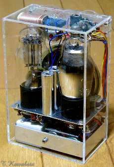
私が
ラジオ作りを始めたきっかけが小学生のころ始めたST管集めだったこともありST管には愛着があり、ST管を使用してできるだけ小さなラジオを作ってみようと思い、このラジオを作りました。もっとも1E7Gは正式にはST管ではありませんが。
内蔵のバーアンテナのみで鉄筋の室内で当地(大阪府寝屋川市)の地元局は全て実用的に受信できます。同条件で夜間は遠距離局も受信できます。
出力管を使用していますが電源電圧が低いので大音量は出ませんが6畳くらいの室内で数人で聞くというような感じの使い方には十分な音量です。
性能、外観共、いま一番気に入っていて、外出時に持ってゆくことも多いのですが電車の中で聞いたりするとちょっと注目されます。
Performance and others.
Many radio wireless fan in Japan love ST-tube, and Many general
public are attracted by its nostalgic and humorous appearance. Because in
Japan, even large manufacturer continued to produce radios using ST tubes until
as late as middle of '50th. And I also love ST-tube. So, I've planned to make
radio using ST tube as small as I can.
All stations
within about 30 miles can be received with built-in bar antenna in my home
(ferroconcrete structure). And at night some distant station can be
received. Because of low B-voltage, audio output is small. But it has
enough volume for listening by few person in small room. This radio
is my favorite one and I often go out with this radio.
戻る
Back