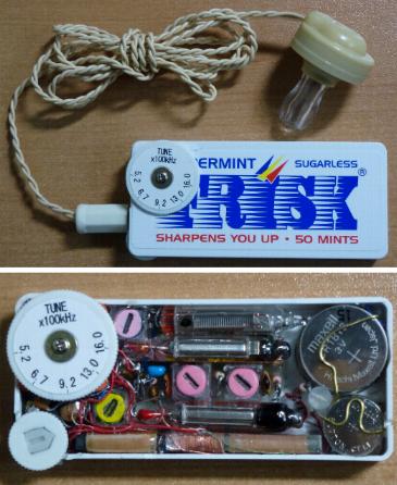
フリスクのケースに組んだ真空管ラジオ
Tube radio in FRISK case
2012年1月完成
completed in Jan. 2012
大きさ:70.3mmx32.1mmx10.6mm(つまみ部除く)
Size: 2.8" x 1.3" x 0.42"(except protrusion of knob)
features:
*Tube radio built in FRISK case.
*It can drive only earphone but is 3 tube super het. with I.F amplifier.
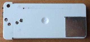
Back side
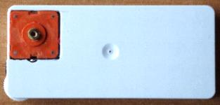
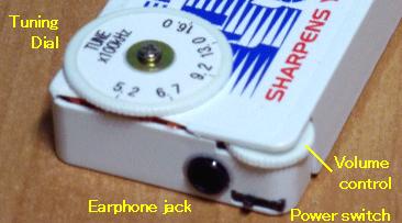
Control part
操作部
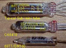
使用球 : CK6418 x2 6977/DM160 x1
回路構成:周波数変換 中間周波増幅 グリッド検波
CK6418 CK6418 6977/DM160
Block diagram: Mixer-oscillator IF-AMP Grid-Detector
CK6418 CK6418
6977/DM160
Tube line up : CK6418x2 6977/DM160 x1
電池:
・A電池: ボタン電池LR44x1 1.5V
・B電池: コインリチウム電池 CR1616x6個 18V
Batteries requirement:
*A-batteries : LR44-AG13 Alkaline Button Cell x 1 1.5V
*B-batteries : Lithium Coin Cell Battery CR1616x6 18V
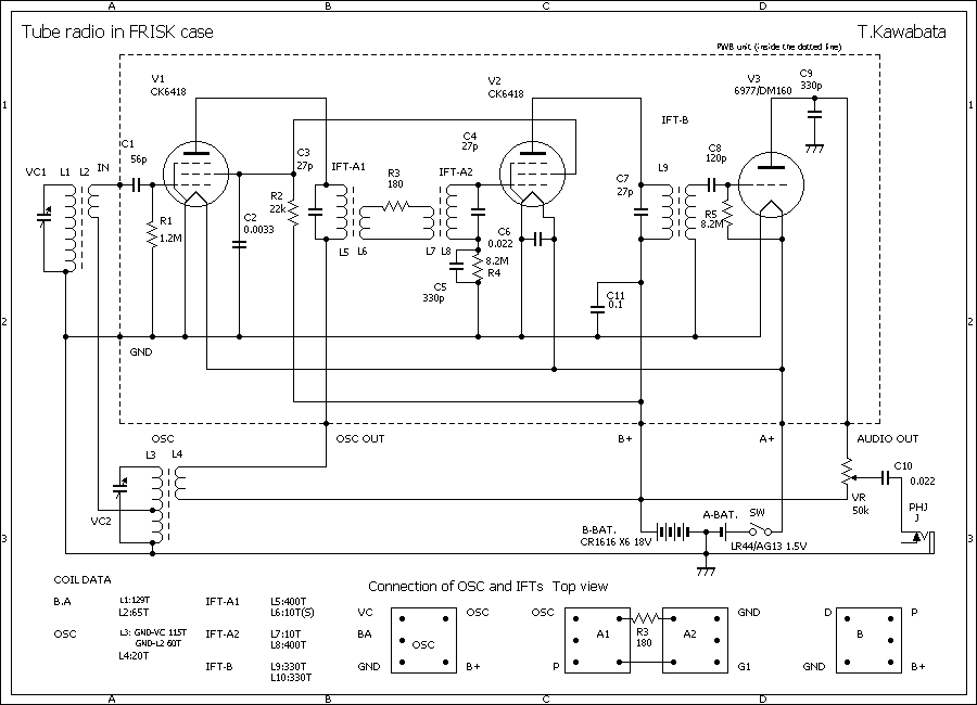
回路について。
CK6418による5極管コンバータと中間周波増幅の後、6977(DM160)でグリッド検波をしています。5極管コンバータは、当HPのほかの回路同様、アンテナコイルにグリッド用巻き線を追加するタイプです。中間周波増幅はごく普通の回路です。
CK6418はもともと補聴器用の球で、普通のサブミニ管よりも小さく、フィラメント電流が10mAと少ないのでこれを使用しました。
6977(DM160)は本当は真空管ではなく表示管の一種で、初期のコンピュータの表示用に作られたものらしいのですが、電極構造と、特性は3極管そのもので、また非常に小型なので、これをグリッド検波に使用しています。表示管なのでプレート電流でプレート(グリッド状ですが。)が緑色に光ります。プレート負荷はチョークコイルがよいのですが、スペースが無いので抵抗(VR)にしています。
最初は周波数変換の後、中間周波増幅無しで再生検波という2球構成を検討したのですが、性能が今ひとつだったのと、スペースがまだ余裕があったので中間周波増幅付きの3球スーパとしました。
構造:
真空管、IFTを含む、回路図の点線の内側の部分はPWBユニットとして、厚さ0.5mmの基板に取り付けられて配線されています。
電池ホルダ、バリコン、電源スイッチ、ボリウム、バーアンテナ、局発コイルを含む回路図の点線の外側の部分は下側のケースに直接取り付けられ、配線されています。
電源スイッチはボリウムの下側になるため、この配線のため、ケースの底側に穴を開けています。また、バリコンのトリマーの調整のための穴もあります。
B電池は厚さがトータル9.6mmあり、そのままでは入らないので、ケースの底をくりぬき、電池ホルダのマイナス極を兼ねる、厚さ0.2mmの錫めっき鋼板で塞いでいます。
バリコンはカバーをはずして使用していますが、それでも厚さが10mmほどあり、入らないので、上ケースをくりぬき、ケースの外に露出させてさせていますが、選局つまみとシールで隠れて目立たないようにしています。
I.F.T、OSCはトランジスタ用の7mm角のものの下部の端子の部分を除き、コアの部分だけを使用して巻きなおしたものを使用しています。端子の部分を除くことにより高さを7.5mmに抑えることができました。
PWBユニットと、下側のケースの部分は別々に組立配線して、最後に合体しました。
感度はそこそこ十分で、内蔵のバーアンテナのみで鉄筋の室内で当地(大阪寝屋川市)の地元の局は全て受信でき、夜間は遠距離局も若干受信できます。
しかし、検波出力で直接イヤホンを動作させ、負荷も抵抗負荷なのでるのであまり大きな音量は得られません。
また、電池が小型で小容量なので電池寿命は短く、特にA電池は1時間程度の寿命です。
実用品には程遠いのですが、真空管でもあの小さなケースに入るラジオを作ることができるという可能性を確かめることができ、当初の目的を達成できたと考えています。
性能、他 :
フリスクのケースを利用していろいろの物を作るのがはやっているという話を聞き、これは当プロジェクトとしてはぜひフリスクのケースに組み込んだ真空管式ラジオを実現させなければならないと考え、設計、製作を開始しました
しかしフリスクのケースは内寸が67x28mmx8.5mmしかなく、とにかくこれに入る構成を考えることにしました。
製作動機、方針
Motive for making this radio and policies :
I heard that making various things into FRISK case is popular, and so,
I think my project should realize tube radio in FRISK case, and begun the
work.
But dimension of inside of the FRISK case is only 67mm x 28mm x 8.5mm (2.6"
x 1.1" x 0.33"), and begin with devising circuit and structure
to make the radio into FRISK case any way.
About schematic:
Pentode mixer-oscillator and I.F amplifier using two CK6418, and after
that is grid detector with 6977(DM160).Circuit diagram of pentode mixer-oscillator
is almost the same with other radios posted on this web site, and that
of I.F amplifier is very ordinary.
Originally, CK6418 was developed for hearing aid, is smaller than ordinary
sub-mini tube and its filament drain is only 10mA, very little, and so
I use this type of tube.
Actually, 6977(DM160) is not a "tube" but a kind of indicator,
it's likely that indicator for computer in early days. But its structure
of electrodes and characteristics are just those of "triode",
and is very small. So I use 6977(DM160) for grid detector. Because 6977(DM160)
is really a indicator, its plate (having structure like grid) glow greenly
by plate current.
Choke coil is favorable for plate load, but having no room for choke coil,
so, resistor (volume control) is used.
At first, I planned regenerative detector directly after mixer-oscillator
using two-CK6418s only (without I.F. amplifier). But its performance was
insufficient, and more, there were still enough room. So I tried 3-tube
super-het having I.F amplifier.
Inside part of dotted line in schematic diagram including tubes, I.F transformer
are built on circuit board of 0.5mm thick and wired, as PWB-unit. All parts
outside of dotted line in schematic diagram including batteries holders,
variable capacitor, power switch, volume control, ferrite stick antenna,
oscillator coil are fit to lower FRISK case directly and wired each other.
Power switch is under the volume control, so, for wiring switch, there
are some small holes at bottom of the case and also holes for trimmers
of variable capacitor.
B-batteries can not go into the case as they are, because. total height of B-batteries is 9.6mm. So, bottom case has hole of same diameter with CR1616 B-battery. and the hole is sealed with tin plate of 0.2mm thick. also work as minus terminal of batteries holder.
Variable capacitor is used without its back cover, even so its height is
about 10mm, and can't go into the case. So, part of top of the case is
cut out and top of variable capacitor is exposed from top of the case,
and hidden by tuning dial.
I.F transformers and oscillator coil are converted from 7mm by 7mm square I.F transformer for transistor, using core only. Its original terminals are removed, and height are lowered to 7.5mm.
PWB-unit and lower case are assembled and wired separately, and thereafter, united each other.
Mechanical Structure:
All stations within about 30 miles can be received with built-in stick antenna in my home (ferroconcrete structure). And at night some distant station can be received. Sensitivity is pretty well.
But earphone is drove directly by output of detector and load of detector
is resistor, so, volume of sound is not so loud. Capacity of batteries
are small, and especially, A battery last only 1 hour or so.
Even though far from practical use, I think my original goal, that is; to confirm the possibility of tubes to make radio in the small FRISK case, are achieved.
Performance and others :
※回路図はあくまで参考です。利用は自由としますが利用により生じるいかなる結果にも責任を負いません。
*Schematic is only a reference and can be use freely But I can't be responsible for any result
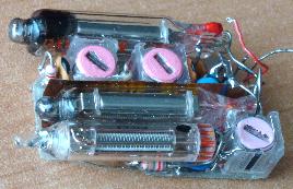
真空管 tubes
6977のプレートが光ります plate of 6977 glow
PWB unit
上面、選局つまみとシールの無い状態
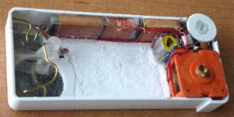
下面、シールの無い状態
Top; without tuning knob and sticker
Bottom; without sticker
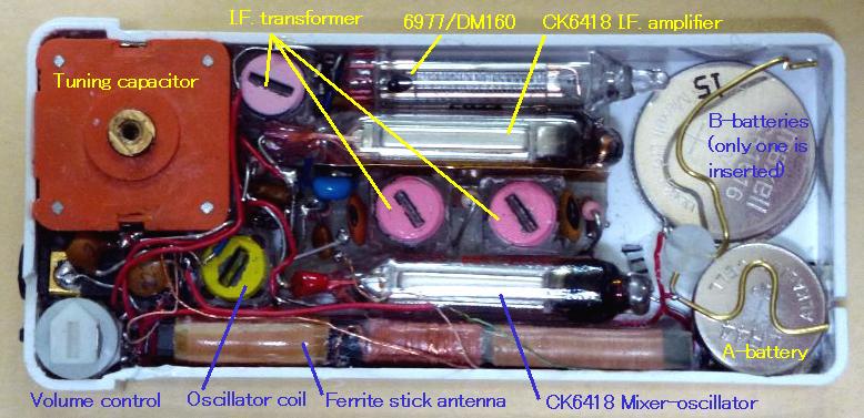
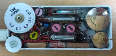
部品配置 Parts arrangement