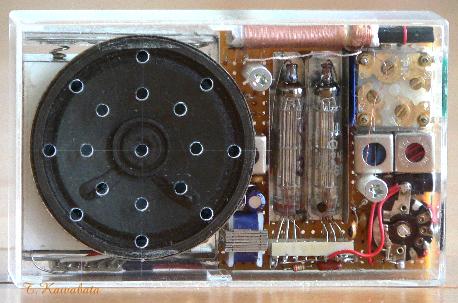
正面
Front view
大きさ:108mmx67mmx31mmつまみ部除く
size : 4.3"x2.6"x1.2"(except protrusion of knob)
旧ソ連製SMT管使用レフレックス2球スーパ
2005年5月完成
2-tubes reflex super-het
using Russian sub-mini tubes
Completed May. '05
正面
Front
view
大きさ:108mmx67mmx31mmつまみ部除く
size : 4.3"x2.6"x1.2"(except protrusion of
knob)
特徴:
1、日本ではあまり馴染みのない旧ソ連タイプのSMT管を使用。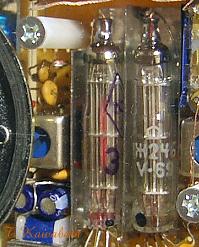
使用球 :
1Ж24Б (1J24B) 1Ж29Б (1J29B)製作動機、方針:
オーストリア在住の友人が「ロシア製サブミニ管を送ってやる」と言ってきて、しばらくして届いたのが本機に使用した2種類のSMT管でした。届くまではそれ程興味もなかったのですが、実際届いた球はなんとなくST管を思わせるような面白い形状で、特性もなかなか良さそうなのでこれを使ってラジオを作ることにしました。
手に入ったのは1Ж24Бと1Ж29Бが、各3本ずつだったので最小限の球数で構成し、面白い形状の球が良く見えるようにするようにしたいとの考えから下記の方針で製作することにしました。
1、1Ж24Бと1Ж29Бを各1本ずつ使用
2、スピーカを動作させ、できるだけ事実用的な性能のものとする
3、大きさはワイシャツの胸ポケットに入るサイズまで許容(当HPの2球ラジオとしては大きい)
4、2本の真空管がラジオの正面から完全に見える。
Motive for making this radio and policies
:
One of my friend lives in Austria E-mail to me that "I will send you
some Russian type sub-mini tubes", and I received some tubes. They are the tubes
I used to make this radio. Until I receive them, I did not have much interest.
But when I received I found they have quite unique and attractive appearance,
somewhat remind me of ST tube. And more, their characteristics seem to be good.
And I decided to make pocket radio using these tubes. I obtained 1J29B and 1J24B
3pcs each. And so, I wanted to make the radio with minimum number of tubes, and
make it so that the tubes can be seen from front of the radio. And to make the
radio, I planned with the policies listed below.
1,Use only 1J29B and 1J24B 1tube
each.
2,Make it will have enough performance
for practical use, with loud speaker.
3,Small
enough to go into shirt pocket.
4,Make it so
that the tubes can be seen from front of the radio.
真空管について:
この種の旧ソ連タイプのSMT管は日本ではあまり馴染みが無いのですが、旧東欧圏あたりでは軍用のストックが放出されているらしく、割とよく見かけるようです。(一人で持ち運ぶ)小型の軍用無線機に80年代まで使用されていたようです。一部にはMig25やMig29等の戦闘機に使用されていたとする記述も見かけますが、電源に比較的余裕のある戦闘機に本当に使用されていたかはちょっと疑問です。
表題を「旧ソ連製」としましたが製作に使用した球の管面に書かれた文字を見ると管名の1Ж24Б、1Ж29Б以外の印字はキリル文字が使用されず、普通のアルファベットで記されているので実際には旧東独あたりで作られたものではないかと思われます。
管名の1Ж24Б、 1Ж29Бは普通のアルファベットでは1J24B、1J29Bまたは1SH24B、1SH29Bと標記されます。
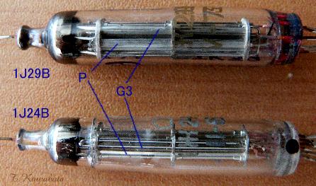
旧ソ連製の真空管は西側の球のコピーも多いのですがこの球は西側のサブミニ管とは全く異なっており、ガラスバルブも途中で太さが変わる面白い形状をしています。また電極は摩訶不思議な構造で、グリッドは全て支柱だけで巻き線(?)がありません。プレートも板金のプレス物ではなく、扁平な断面の棒です。
特性は1Ж24БがIf=13mA、gm=1000位の小信号用、 1Ж29БはIf=60mA、gm=2000位の電力増幅用(といっても出力は数十mW程度ですが)のようです。
About tubes :
In Japan this kind of the SMT tube of old
Soviet type are not popular, but it seems that around the old the Eastern Block
countries, military stock are released and can be seen frequently. It is likely
that this kind of tubes are used in small military radio communicator until
'80th. And some descriptions can be seen state that this kind of tubes are also
used in some equipments of Mig-25 or Mig-29 fighter plane. But it is
slightly a question whether it was alike and really was used. Because I think
Jet fighter plane has too powerful power supply for this kind of 1.5V dry cell
type sub-mini tube.
Although the title was made into "Russian sub-mini
tube", I think they were made in old Eastern Germany really, or in some other
old eastern countries. Because There are no other Cyrillic letters except the
tube number.
Tube number 1Ж24Б,1Ж29Б are described 1J24B, 1J29B,
or 1SH24B, 1SH29B at the ordinary alphabet.
Although the Russian type tubes
also has many copies of a western tubes, these tubes are completely different
from the western sub-mini tubes. And they have Interesting appearance that their
diameter of glass bulb changes on the way. Moreover, electrodes has mysterious
constructions, all grids are only support rods and have no winding; rateral
constructions.
Plates are also rods of rather flat cross section, not pressed
sheet metal.
As for the characteristic, 1Ж24Б is; If=13mA, the gm=1000 for
small signals, and 1Ж29Б is power pentode, If=60mA and gm=2000.( even if it
says, "output pentode" its output is about tens of mW) -- like .
使用した真空管1Ж24Бと1Ж29Б
Tubes used to make this radio 1Ж24Б and
1Ж29Б
球の電極構造の横断面(よこだんめん)の模式図
Typically written lateral cross
sections of electrode structure of these tubes.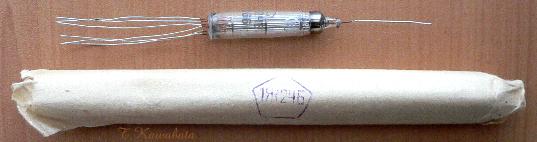
パッケージ
Package
回路図
※回路図はあくまで参考です。利用は自由としますが利用により生じるいかなる結果にも責任を負いません。
schematic
Schematic can be
used freely. But it is only a reference, and I can't be responsible for any
results.
回路について:
5極管2本でスピーカを動作させる回路構成はいくつか考えられるのですが、この大きさ、形状では再生検波はなんとなく馴染まないと個人的には思ったのでスーパとすることにしました。5極管2球でスーパとするにはダイオードを使用しなければならず、ちょっと抵抗があったのですが、1と2の目的を達成するためにはやむを得ないものと、割り切りました。
周波数変換は1J24Bによる5極管コンバータで、回路は当HPの他のラジオでよく使っているものです。OSCコイルの巻き線仕様も他ラジオのものとほとんど同じです。このラジオに使用したバリコンはダイソーの300円ラジオのもので、これは何故かFM/AM用の4連バリコンで、AM部は等容量の2連になっています。このため局発側のバリコンにはパディングコンデンサ相当の固定コンデンサが直列に入っています。
中間周波増幅と電力増幅は1J29Bで行っています。電圧増幅はなく、検波出力が直接電力増幅管に入力されます。1J29Bは一応電力増幅管なのでバイアスが深く、グリッドリークバイアスでは使用できないので、バイアス回路を設けてあります。
経験上、検波出力とレフレックスのAF入力との間に結合コンデンサを入れると再変調によりAFの発振を起こす場合が多いので、検波出力は直結で1J29Bに入力される形になっています。このため、検波回路のGNDにはDC的には出力管のバイアスがかかっています。検波出力が直結で1J29Bに入力されるため、AVC電圧も1J29Bに入力されボリウムを廻すと1J29Bのバイアスが変化してしまいますが、実用的には特に問題もなかったのでそのままにしています。
IFTは2箇所とも単同調として、トランジスタラジオ用のIFT2個だけで済ませています。このようにしても選択度はそれ程問題はないのですが、局部発振の出力が中間周波増幅回路に極端に漏れ出さないことを確認しておく必要があります。以前、同じような回路構成のラジオを作ったところ、受信周波数600KHz近辺で極端に感度が悪く、調べると局発の発振勢力がこの近辺の受信周波数で、中間周波増幅回路にかなりのレベルで漏れ出していました。このときのIFT−Aの巻線仕様は1次側2次側共、300Tだったのですが、同調コンデンサの無い2次側が1000KHz付近で共振を持っていたようで、1次側400T、2次側200Tとしたところそのような現象が収まりました。このラジオでも1次側400T、2次側200Tというやや変則的な仕様になっているのはこのためです。しかし本来はIFT−Aは複同調にすべきと思います。
About schematic :
There are
some other radio circuits that can drive loud speaker. But I think regenerative
circuit is mismatched for the radio of this size and appearance. And so I adopt
super heterodyne circuit. I do not want to use semiconductor diode in tube
radio. But It is very difficult to make super-het with only two pentode. And I
made a compromise.
Frequency changer is pentode converter I often use, with 1J24B.
Coil data of OSC is also same with other radio posted on this web site.
Variable capacitor of this radio happened to be FM/AM transistor
radio type. Of course, FM part is not used. Two variable capacitors for AM
section have same maximum capacitance(not "trackingless "type) , and so,
capacitor of fixed capacitance of 180pF is connected series to variable
capacitor for oscillator part.
I used 1J29B for IF and audio power AMP and
omit AF AMP. And output from detector go to audio power AMP
directly. Grid leak bias is not suitable for 1J29B, because 1J29B needs
relatively large bias voltage. And so, bias for 1J29B is made from total
B-current of this radio.
In reflex circuit, IF signal is tend to be modulated
by AF signal which is amplified in same tube. When input signal is large, this
modulation may cause harmful audio oscillation. To avoid this harmful audio
oscillation, there is no coupling capacitor between detector and power-AMP. So,
GND of detector is DC potential of grid bias of 1J29B. Output of detector is
connected to G1 of 1J29B without coupling capacitor. And so, AVC voltage at G1
of 1J29B varies according to rotation of volume control knob. But it do not
cause practical trouble.
Two IFTs are both single tuned type. I use one
transistor-radio-IFT for each of them. Even in this case, selectivity is not so
bad. But it necessary to confirm that signal from local oscillator do not leak
out to IF stage seriously. Once I made a radio having similar circuit, but
sensitivity of the radio was very poor around 600kHz. Its local oscillator
signal leaked out to IF stage when receiving around 600kHz. Turn number of
primary and secondary winding of IFT-A of this radio were both 300T. And
secondary winding without tuning capacitor had resonance frequency of around
1000KHz. So, I changed winding of IFT-A to primary 400T and secondary 200T,
therefore the trouble was solved. Based on this experience, I adopt this rather
odd coil data also for IFT-A of this radio. But I think IFT-A should be double
tuned type.
電池: ・A電池:単3x2 (並列) 1.5V
・B電池:コインリチウム電池CR2025x15個 45V
※通常はDC−DCコンバータユニットを使用。
Batteries
requirement:
*A-batteries : AA-cell x 2 (parallel)
1.5V
*B-batteries : CR-2025 coin lithium cell x 15
45V
I've made DC-DC converter unit for B-voltage
supply
and use it for daily use.
使用部品:
・バーアンテナ、バリコン、IFT、OSC、イヤホンジャックはトランジスタラジオ用のもの
を使用。但し、コイル類の巻線は変更。
・出力トランス−−ST30(相当品)の改造(巻線の変更)。
・S付VR 1MΩ : スイッチ1回路1接点のものをそのまま使用
Parts:
*Main parts are parts are parts for
transistor radio. All coils are altered.
*Output
transformer--Remake of ST-30 (equivalent type)
*Volume control 1Mohms
with 1 pole 1throw switch, I use it as it
is.
外装 :2mm厚、1.4mm厚の透明アクリル板で自作
Casing : Hand made, made of
clear acryl plate thickness of 2mm and
1.4mm.
シャーシ :金属製のシャーシはなし。ユニバーサルプリント基板を使用
Chassis
: Using PWB, has no metal
chassis
つまみ類 :トランジスタラジオ用の既製品
Knobs :Ready-made
articles for transistor radio.
外装、構造 :
スピーカ、電池ホルダ以外の回路部品が1.6mm厚のガラエポユニバーサル基板に取り付けられて、これがケースにスペーさを介してねじ止めされ、電池ホルダはケースに嵌め込まれています。スピーカ両面テープでケースに固定されています。
回路基板は部品面側にほぼ全ての部品が取り付けられており、球が前側から見えるように部品面側を前側にしてケースに取り付けられています。球は16pのICソケットに挿されており、球の周囲にはシールド板があります。電池ホルダにはスピーカへの接続コネクタ、DC−DCコンバータへの電源供給用のコネクタ、回路基板との接続コネクタが設けられており、回路基板、スピーカ、DC−DCコンバータの結線は全てこの電池ホルダに設けられたコネクタを介して行われています。
ケースは各部品が取り付けられる箱型の本体に板状の裏蓋が付く形になっており、前面板のみ2mm厚、他は1.4mm厚のアクリル板で作られています。当初、「SMT管式レフレックス3球スーパ」のように板状の前面板に箱状のバックカバーをかぶせる構造にしようと考えていたのですが、このように部品面側を前側にして基板を取りつけるとVRやバリコンのつまみが後ろ側になり、箱型のバックカバーだと開閉が非常にやりにくくなることに気づいたので、このような構造にしました。
Casing and construction :
All electronic
parts except speaker and batteries holder are fixed onto PWB thickness of 1.6mm.
And this PWB is fixed to Casing with screws. And batteries holder is snapped
onto case. Speaker is adhere to case.
Almost all electronic parts are fixed
onto parts side of PWB. And PWB are fixed to case so that the tubes can be seen
from front of radio. Two tubes are inserted into 16p IC socket. And there are
shield plates around the tubes. Batteries holder has connectors for speaker,
DC-DC converter, and PWB. Each of these units are wired through these connectors
on Batteries holder.
The
case consists of box shaped body to which all parts are attached, and flat back
cover. Case is made of acryl plate thickness of mainly 1.4mm. Only front
plate has thickness of 2mm. At first, I planned flat front panel to which
all parts are attached, and box shaped back cover. But when PWB is arranged its
parts side to the front of the radio, knobs for tuning and volume control are
positioned near the back side of the radio. Then I found that in such
a construction it will be very difficult to avoid interference between these
knobs and the box shaped back cover when open or close the cover. And I adopt
flat back cover.
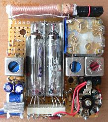
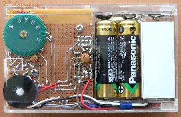
回路基板 部品面側
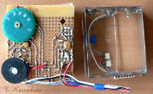
回路基板 パタン面 と 電池ホルダ
PWB Parts
side
PWB pattern side and batteries holder
Performance, others
:
In respect of mechanical structure, it was made to see
all the tubes from the front, and small enough to go into shirts pocket, and the
case made of acryl was also finished finely and firmly, I think it was success
at these point. But an inside has many useless spaces and a little redundant
touch cannot be denied.
In respect of performance, I
think not so bat as radio of only two pentodes. Although volume was not so
large, when it was the usage heard alone, the volume level which can be used
practical was obtained.
It is relatively sensitive. All local stations
within about 30 miles can be received with built-in bar antenna in my home
(ferroconcrete structure). And at night some distant station can be received.
back