I want to understand the claim of an artist and the creator by revitalizing a original sound (in Hi-Fi) as much as possible.
◎ Past step
1970, QS system was announced from SANSUI. I made the QS decoder in reference to QS-1 was released at that time. I copied (According to Cds and lamp) the phase-modulation. Unfortunately, phase modulation (rear does not sound localization) of QS-1 had a slightly unreasonable.
1971, SQ system was announced from CBS-Sony.
1976, SQ system was withdrawal.
1986, QS system was withdrawal. The subset remained as Dolby system.
1989. My own professional logic Dolby decoder and the circuit. And, decoder is no continuity to front and rear. In addition, it is the system for movies only. Rear channels are for only playback of sound effects. (it is a standard not suitable for music playback)
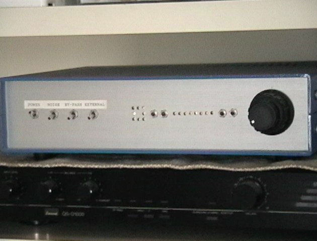
2003. Therefore it is QS4ch/SQ4ch decoder, the inside and the circuit to have remade. From the left an input selector (the back, decoder, three system outside 4ch input). A sound field turn. SQ/QS choice. A matrix coefficient. A previous level. Back level. A result of the audition, QS has become practical, however, SQ did not become entirely practical without separation.
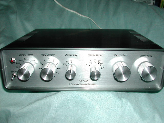
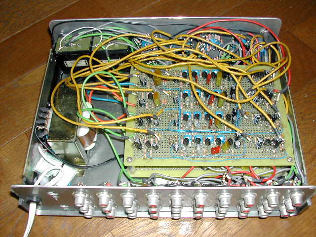
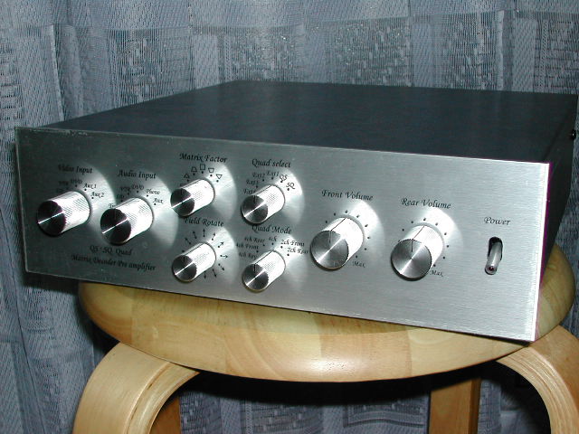
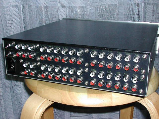
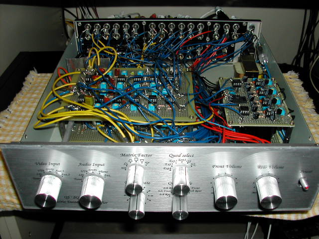
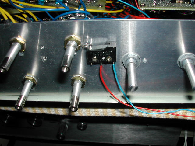
2004. And it is the front of the new QS4ch/SQ4ch decoder which it remade, the backside, the inside, the connection diagram in what wanted to let you have an equalizer and the video selector built-in newly. (By lack of the point of contact number of switches, the change of QS/SQ detects an axial turn and changes it through a relay) However, the initial version that did not use op-amp for sound quality was much better. It is a video input selector, an audio system input selector, a matrix coefficient from the left. A sound field turn. A Quad input selector (four system outside 4ch input, QS, SQ), a mode change, a previous level. Back level. Here, SQ without logic, it was found that even with increased precision, useless. Therefore, it was started the development of logic SQ.
2006. Came up with the separation improvement logic proposal of Sony SQ method. When confirmed by experimental circuit, found it to go well is. Decided to implement it from the next time.
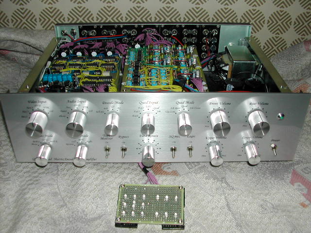
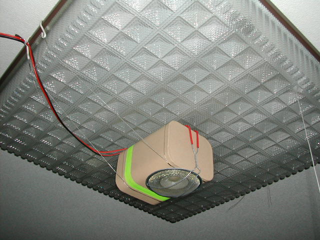
2007. QS4ch/SQ4ch/QS6ch logic decoder which the top and bottom considered, a decoder with logics. The front, the inside, the connection diagram(During the modification). From the left video input selector, stereo mode, audio system input selector, 2ch mode, decode mode, tape monitor, bypass, Quad input selector (4 system outside 4ch input, QS, SQ), sound field turn, Quad mode, SQ mixture, logic ON/OFF, Front level, upper level, Rear level, lower level.) The details. Thus, the validity of the design logic of the QS4ch and SQ4ch could be confirmed. In addition, by logic, to withstand practical use was also found SQ4ch. However, the logic of QS6ch was able to confirm the effect, but the logic needed to be reexamined. (Since it was confirmed that there was a discontinuity in the sound field space on 6ch, and that a problem occurred in logic processing due to it ...) In addition, although the ceiling speaker is installed directly above, the distance from the ceiling (especially because of a Japanese house) becomes short, and it is inevitable that the volume balance will be greatly disturbed at the height of the head. Therefore, it was also found that there is a fundamental problem in the method itself.
Note: Discontinuity means that if you encode a sound that moves without interruption in the order of front → directly above → directly behind → directly below → front → directly above →, the left and right phases will rotate endlessly. Therefore, it means that discontinuity points must be generated on the way.
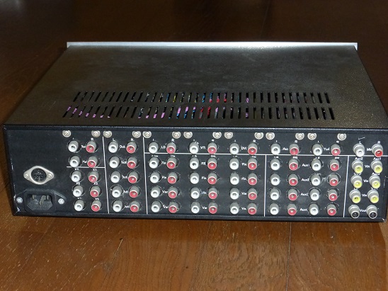
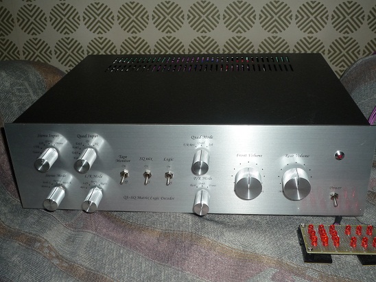
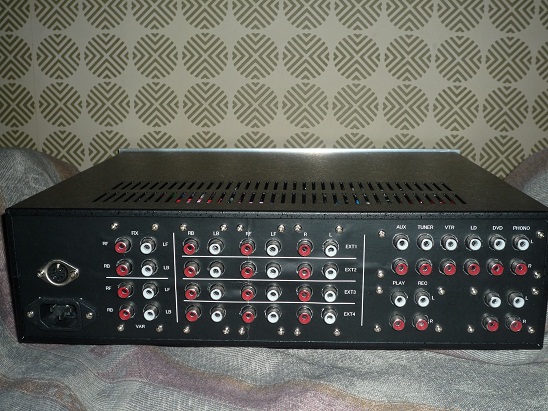
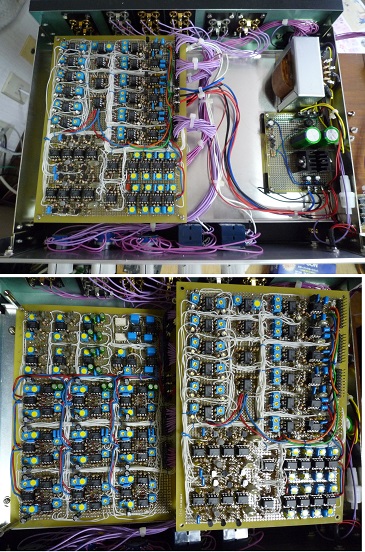
2011. Since QS4ch/SQ4ch/QS6ch logic decoder was over-specs, it remade, QS4ch/SQ4ch logic decoder. The front, the backside, the inside, the block diagram, the connection diagram. From the left audio system input selector, stereo mode, Quad input selector (4 system outside 4ch input, QS, SQ), 2ch mode, tape monitor, SQ mixture, logic ON/OFF, Quad mode, F/R mode, Front level, Rear level.) Although no less than 60 pieces are using the dual operational amplifier, sound quality degradation is slight (if compared with sound quality degradation at the time of the A/D conversion of the digital sound source itself). However, the logic of QS6ch was needed re-examination. (Because there was a flaw in the logic processing of discontinuous space) In addition, it is a ceiling speaker installed directly above in the experiment at that time. However, since the distance to the ceiling is getting closer, the volume balance is lost depending on whether you sit or stand, and it was found that there are some practical obstacles to the method itself.
2012. For comparison with the Sansui QSD-1, also with it,
has produced SQ4ch logic decoder the audio band is divided into three, put the
logic for each. In addition, the QS4ch system was not a problem for practical
use even if there is no logic. Therefore, the QS4ch system is not put the
logic. Front, behind, inside, the block diagram, the connection diagram. From left to right, decode mode, input selector, Quad mode, Front level, Rear
level. Using a dual op-amp 81 pieces.
Compared with the SQ4ch logic decoder was manufactured in 2011,
improvement of sound localization has been achieved.
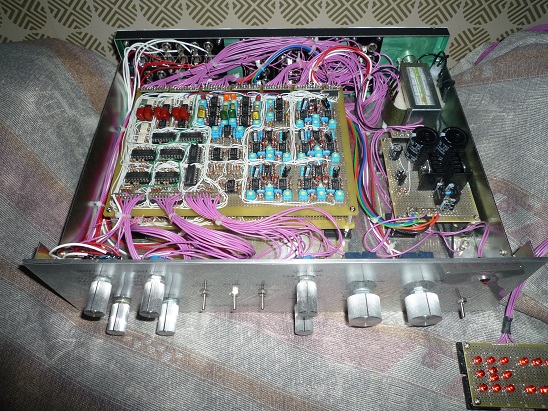
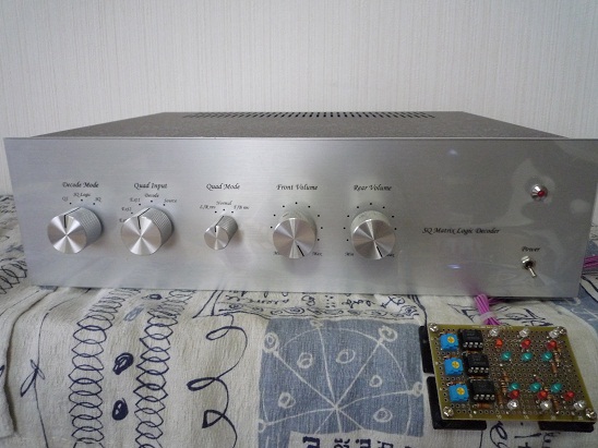
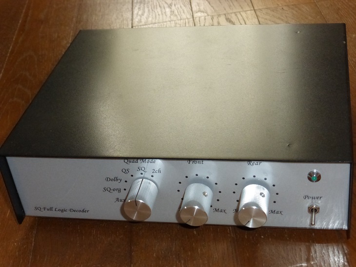
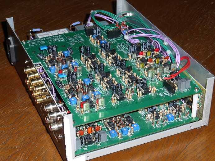
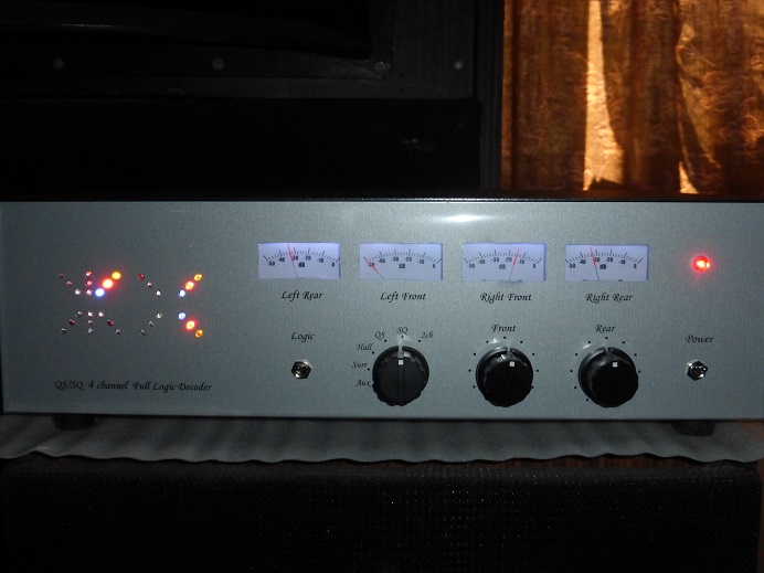
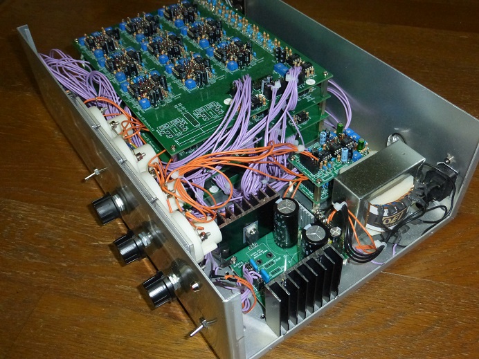
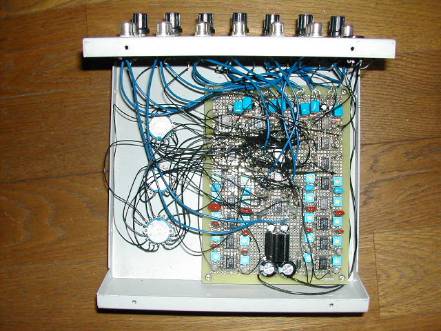
2015. Again, produced the SQ logic decoder that does not split the ordinary band. This time we made in the printed circuit board. front, inside, circuit diagram. QS decoder is no logic.
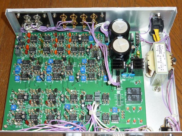
2016. The SQ decoder that was manufactured in 2015 and was expanded the QS logic. front, inside that added the printed circuit board to the second floor, (Duplicate circuit was deleted) circuit diagram.
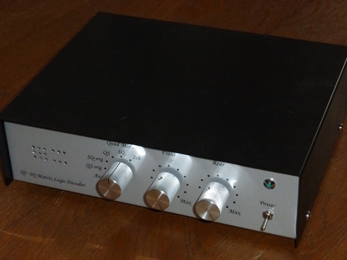
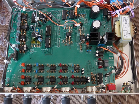
2018. Both QS and SQ divided the band into three, and completed the QS / SQ decoder which puts the logic individually in each. This time I made it with printed circuit board. front, inside, and, the block diagram, circuit diagram.
As a supplement, as a room for improvement, distortion can be improved (at large amplitude) by optimizing the amplitude for the VCR.
By the way, measure the frequency characteristics/separation of various decoder. As of the measurement result, the frequency characteristics of the manufacturer-made decoder, it was found that not very flat.
Supplement
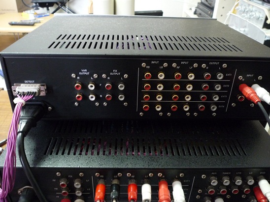
The
QS4ch/SQ4ch/QS6ch encoder that I produced as a machinery for adjustment, the front, the rear, the inside., the connection
diagram. I made a new printed circuit board. It is a circuit.
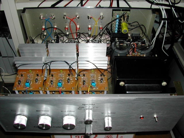
Both
the QS method and the SQ method were designed so that the center left side
sound and the center right side sound properly generate the encode signal. (6 channel main amp and the
connection diagram which are connected to this decoder for your information)
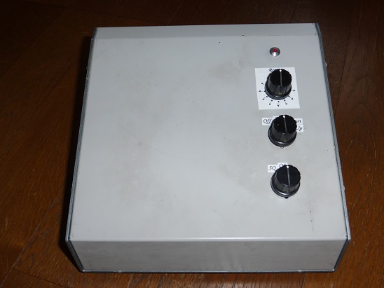
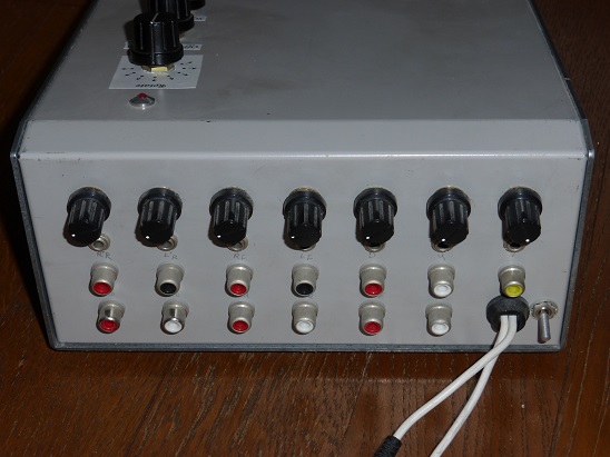
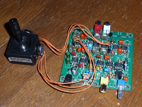
2022. I made a surround pan
pot with a printed circuit board. That circuit.
This is an example
of its operation.
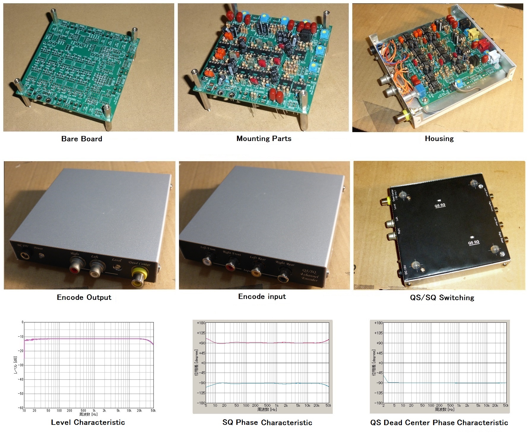
2023. Also,
I made a new QS/SQ
4ch encoder on a printed circuit board. That circuit.
Test
signal (noise)., Rotate 10 second intervals (Front,RightFront,Right,RightRear,Rear,LeftRear,Left,LeftFront,(OverHead)):
RT.zip (6.6MB).
(Note: In SQ the sounds over head can not be transmitted theoretically
correctly)
◎ The commentary of various matrix methods
QS4ch method, an SQ4ch method, a QS6ch method, each encode / decode expression are as follows.
・
The
encoding / decode calculating formula of the QS4ch method
L = 0.924 * LF + 0.383 * RF + 0.924 *
LR * i + 0.383 * RR * i
R = 0.383 * LF + 0.924 * RF - 0.383 *
LR * i - 0.924 * RR * i
LF = L + 0.414
* R
RF = R + 0.414
* L
LR = (L - 0.414 * R)
* (-i)
RR = (R - 0.414 * L)
* ( i)
Localization improvement method (Rear ch +-60degree phase shift)
LF = L + 0.414 * R
RF = R + 0.414 * L
LR = ( L – 0.414 * R ) * (0.5 - 0.866
* i )
RR = ( R – 0.414 * L ) * (0.5 + 0.866
* i )
・The encode / decode calculating formula of the SQ4ch method
L = LF -0.707 * LR * i + 0.707 * RR
R = RF -0.707 * LR + 0.707 * RR * i
LF = L
RF = R
LR = 0.707 * L * i - 0.707 * R
RR = 0.707 * L - 0.707 * R * i
Symmetric improvement method
LF = L
RF = R
LR = -0.5 * L * ( 1 – i ) - 0.5 * R *
( 1 + i )
RR = 0.5 * L * ( 1 + i ) + 0.5 * R * ( 1 – i )
・The encode / decode calculating
formula of QS6ch methods ( Under review )
L = 0.924 * LF + 0.383 * RF + 0.924 *
LR * i + 0.383 * RR * i + 0.65 * ( 1 + i ) * UP + 0.65 * ( 1 – i ) * DN
R = 0.383 * LF + 0.924 * RF - 0.383 *
LR * i - 0.924 * RR * i + 0.65 * ( 1 – i ) * UP + 0.65 * ( 1 + i ) * DN
LF = L + 0.414 * R
RF = R + 0.414 * L
LR = ( L - 0.414 * R ) * (-i)
RR = ( R - 0.414 * L ) * ( i)
UP = -0.707 * L * i + 0.707 * R
DN = 0.707 * L - 0.707 * R * i
Symmetric improvement method
LF = L
+ 0.414 * R
RF = R
+ 0.414 * L
LR = ( L
- 0.414 * R ) * (-i)
RR = ( R
- 0.414 * L ) * ( i)
UP = 0.5 * L * ( 1 – i ) + 0.5 * R * ( 1 + i )
DN = 0.5 * L * ( 1 + i ) + 0.5 * R * ( 1 – i )
◎ Others
list of software during the
evaluation.
Supplement
Among the commercially available SQ
decoders, the ones that operate closest to the self-made machine were the Tate
II 101a manufactured by Fosgate (also a crosstalk canceling method) and the
SurroundMaster manufactured by Involve. (As a result of comparing and
auditioning the three, it was confirmed that the operation was almost the same
as the self-made machine)
The
Sony SQ decoder is a logic wave matching method that mutes the rear when the
sound source is in the front and mutes the front when the sound source is in
the rear. As a result of the audition, the sound source direction emphasis
ability was a little low, and it was often not possible to decode
correctly. (Because it is designed
to mute the low volume side, all the sound sources on the low volume side will
move to the high volume side, and the whole will flutter back and forth,
especially in a large orchestra.)
etc.